TRRSTAN, along with some other Cellbots, will be at the Maker Mini Faire in Denver Colorado, this Sat, July 17
If you want to drive a cellbot come on down. We have a special treat for drivers.
TRRSTAN, along with some other Cellbots, will be at the Maker Mini Faire in Denver Colorado, this Sat, July 17
If you want to drive a cellbot come on down. We have a special treat for drivers.
If you have been thinking about building your own Cellbot, the barrier to entry just got even lower.
Introducing TRRSTAN, the audio controlled Cellbot:
TRRSTAN is now for sale on the inventor’s site: robots.allthingsgeek.com
Truckbots are still available at the cellbots store.
Look for a full post explaining how TRRSTAN works soon.
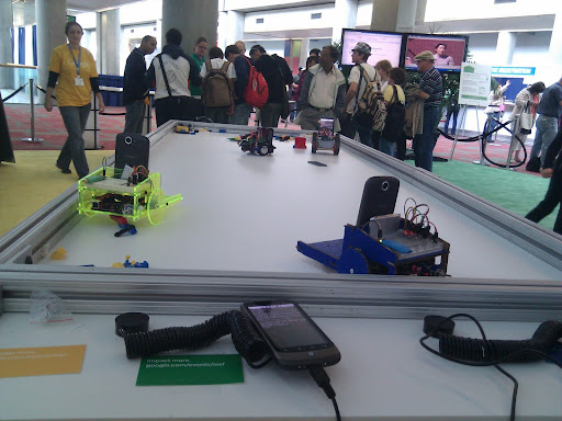
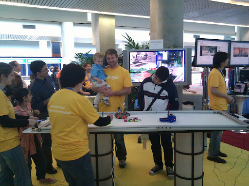
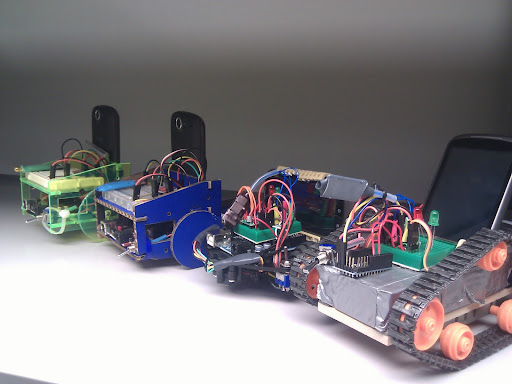
We’re thrilled to be demoing our Android Cellbots at the 2010 Intel International Science & Engineering Fair this week in San Jose, California. Thousands of people will be dropping by the Google booth to play with four of the robots and learn how they work. The kids are having a blast and the parents are jealous they couldn’t do things like this at their age.

We have some video streaming from the phones to the big screen TV and people can also use the remote to trigger still pictures to be snapped. The demo shows off the use of Android Nexus One phones as remote controls using the accelerometer to drive the robots. That sends XMPP commands over Google Chat to another Nexus One on the robot, which act as the main brain. That phone then sends commands over Bluetooth to the robot hardware.

We hope the excitement continues and we see more kids making Cellbots this summer. Our parts lists for the Android robots and the source code project site can help you get started. Those short on time can also check out our robot kits page where we can put together a package for you. Then be sure to jump in on the discussion list to ask questions and share news of your projects!

Getting this demo ready was a big team effort that took a lot of work to go from short five minute demos to having four robots run all day for a week. Damon Kohler came through with awesome upgrades to last week’s Android Scripting Environment. Charles Chen was extremely helpful in getting the video and still image streaming setup, and used some code from Darrell Taylor’s work. Jason Holt, maker of the Boxbot, helped with the remote control mathematics and getting the demo table ready. Tim Heath upgraded the kits page for those of you interested in using one of our designs, and Glen Arrowsmith’s recent Arduino code that saved calibration data to the EEPROM was critical. Many thanks to you all!

If you are in the San Jose area this week, be sure to stop by the convention center on Thursday May 13, when the International Science and Engineering Fair is open to the public from 9am to 9pm.
We’ve simplified the Tankbot so much that this has to be one of the simplest and cheapest robots around. Instead of a 5v Arduino, which needs 3.3v to 5v logic level converting, we’re using a 3.3v Arduino Mini Pro. The TX and RX pins can connect directly into the HTC breakout board on the bottom of the Android G1 for serial communication.
The only tricky part was getting a thin 30 gauge wire to run into the back of the phone and wrap around the positive battery terminal. We tried some thicker wire at first but it prevented the phone from maintaining a connection and it would shut off accidentally. The thinner wire sits there nicely and we might try making a permanent connector on the outside of the phone so it can fit back in a pocket without a wire sticking out.
The top picture is a working version with the red 30 gauge wires above is an early test with a thicker green wire that had a flaky connection. You can see that we’re still using the HTC breakout board wiring for TX, RX, and ground, and we’re not yet connecting the fourth wire that you see here. That would be used for charing the phone but doesn’t provide enough power out to run the robot.
This video overview shows you the whole thing moving around to prove it works. No word yet on the effects of doing this on your battery so please do so at your own risk.
If you get something similar working, share it in the Cellbots support & discussion group. Bonus points if you hook your robot up to a wireless charging station!
Most projects using a 5v Arduino board for robots are going to run into some 3.3v circuits at some point. This might be the serial line coming from a G1 Android phone or an inexpensive Bluetooth module. To deal with this properly you’ll want to be able to convert the voltage going in and out of the Arduino to work properly with these devices.
Let’s look at two options, starting with the least expensive, but more complicate method we started with in 2009. This involves using a $0.25 hex inverter chip such as an 74LS04 chip and two resistors. We used this to send the 3.3v signal from the phone into the chip, back out at 5v but inverted (0’s were 1’s and 1’s were 0’s), and then through again to come out properly at 5v.
Handling the 5v to 3.3v side of things is even easier with two resistors. We used a 20k and a 39k resistor as described here on Make Things, but we’ve also used a 1.8k and a 3.1k as described here. Both did the job just fine and made sure we didn’t fry our phone or Bluetooth module.
The above method has served us well but we’re moving on to using this $2 logic level converter from Sparkfun.
It supports two channels of conversion and we’re only using one so far. You simply connect it to your 3.3v and 5v power sources and it handles converting the signal in and out. You can use the Arduino for both power sources since they typically provide you one of each level, even though the RX/TX pins are always 5v. All you need is a little soldering when you get the board to connect the header pins and it will plug right into your breadboard.
Some of you have pointed out that the Arduino will often treat as 3.3v RX serial input just fine. We’ve tested this as well and found it usually works. You’ll still want to lower the returning TX voltage going back down to 3.3v to not damage your phone or Bluetooth module. To be safe though we recommend using the proper conversion each way to avoid headaches by eliminating the chances that something isn’t reading right.
We’ve posted some additional pictures of what we’re doing in our gallery and embedded it below for convenience. Read the captions to see what is going on in each shot and reach out to the Cellbots discussion group if you need a hand or want to share some tips of your own.